
Installing the FERRO Underfloor Heating Manifold – Step by Step
Why is the manifold crucial in an underfloor heating system?
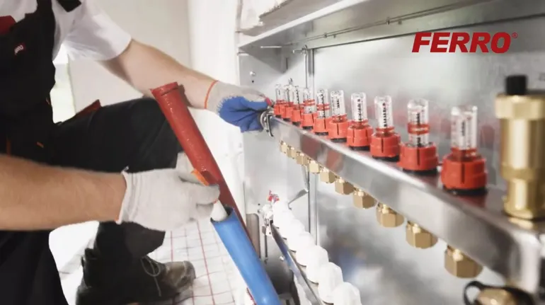
The manifold is the heart of an underfloor heating system—it ensures even heat distribution to all heating loops. When properly selected and installed, it enhances the system’s efficiency and ensures trouble-free operation.
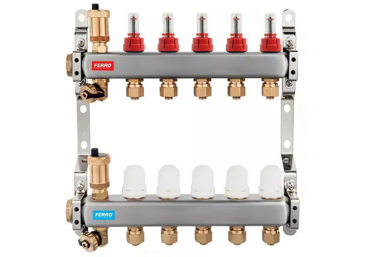
FERRO SN-RZP 1" manifolds, made of stainless steel, are ready-to-install kits with factory-installed thermostatic valves, flow meters, air vents, and drain valves. By purchasing such a ready-to-install kit, you save time and minimize the risk of installation errors.
Preparing to Install the Manifold
Before you begin installation, make sure the in-wall cabinet is properly leveled and mounted. You can learn how to install a FERRO cabinet in the previous article.
What you should know:
- The FERRO manifold comes in sturdy packaging that protects it from damage during shipping.
- By default, the air vent and drain assemblies are located on the left side, but if necessary, they can easily be moved to the right.
Before installing the manifold:
- Check that the kit is complete.
- If the system layout requires it, move the entire manifold or just the air vents to the right side.
- Install the shut-off valves—a straight valve with a thermometer on the supply line and an angle valve on the return line.
FERRO offers F-Power valves designed specifically for this purpose, featuring a 1-inch threaded connection and a seal using an O-ring and a lock nut:
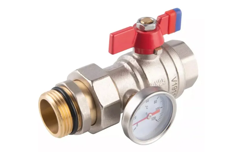
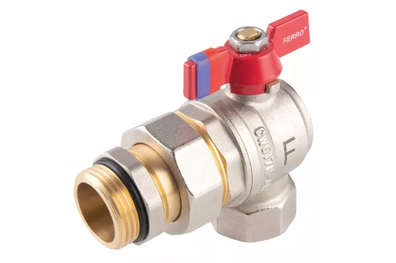
Features of F-Power valves:
- 1" threaded connection with an EPDM O-ring seal—no need for Teflon tape or packing.
- Precise fit with the milled grooves in the manifold body.
F-Power Valve Installation Instructions:
- Screw the valves onto the manifold beams.
- During installation, the valve ball must be in the open position.
- Use a wrench to grip the valve’s octagonal shank from the side where the pipe or fitting is screwed in (never from the opposite side).
Installing the manifold in the cabinet
After equipping the manifold with F-Power valves, you can proceed with installation in the cabinet.
Step by step:
- Loosen the nuts securing the rails in the cabinet.
- Slide the rails apart to adjust their spacing to match the manifold’s mounting brackets.
- Place the manifold onto the mounting screws.
- Tighten the nuts and check that all components are accessible.
Tip:
Maintain adequate spacing between the manifold beams and the cabinet walls—this will facilitate the subsequent installation of heating loops and any future maintenance.
Connecting the System
Once the manifold is installed in the cabinet, you can proceed with connecting the system.
What needs to be connected:
- Supply and return lines from the heat source—to the F-Power valves.
- Heating loops – to the manifold’s ports using FERRO screw-on fittings (Euroconus). Read the article to learn how to do this.
- For systems with zone control, install the thermostatic heads:
- Unscrew the white knobs from the return manifold.Screw on the FERRO thermoelectric heads compatible with the control system.
You can find more expert advice on the FERRO PRO YouTube channel